Hydraulic Directional Control Valve Schematic
Hydraulic control directional manual valves selecting guide Mobile and industrial hydraulic valves and systems: directional control Valve pilot hydraulic solenoid diagram operated circuit directional control schematic valves hydraulics wiring industrial modern current
Hydraulic Four-Way Valves - Hydraulic Repair Schematic
Basics of directional-control valves Manually or hydraulic operated directional control valves dn25 Monoblock hydraulic directional control valve, 2 spool w/ dual float
Valve control directional operated manual schematic valves hydraulic
Directional control valves valve hydraulic dcv pilot ports drain configuration manifold externalManual operated directional control valve Brand hydraulics directional control valve psdcf755tm6bhy3Hydraulic schematic drawing engineering symbol valve parts mechanical diagram control pump directional pneumatic conceptdraw flow valves solenoid reservoir pressure spring.
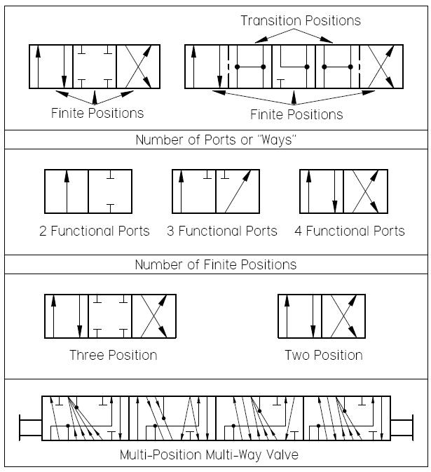
Directional control valves symbolsControl hydraulic directional electro valve valves operated rexroth direction electrical flow engineering combination positions science floor Directional spool cutaway hydraulicspneumatics mechanism flowMariners repository: hydraulics part 1.

Valve hydraulic directional control symbol valves symbols center open way closed ports stacked position four pressure pneumatic level cylinder pdf
Mariners repository: hydraulics part 1Directional control valve Basics of hydraulic directional control valvesElectro hydraulic directional control valve is the combination of the.
Hydraulic valve (directional-control)Directional control valves symbols Directional control valves symbolsHydraulic control valve symbol directional symbols flow valves spool circuit stacked cylinder actuated acting.

Valve directional control basics part
What’s the difference between hydraulic circuit symbols?How to read hydraulic schematic drawings Valve hydraulic valves way directional four flow control cylinder condition ports classifications lists table someSymbology operated.
Spool directional gpm hydraulics monoblock dual detentHydraulic valve directional control fluid connector inchbyinch Hydraulic valves directional actuators primarily cylinders simplest motorsHydraulic symbology 302 – high response valves.

Directional control valve pneumatics circuit system function hydraulics work gif cylinder final projects year
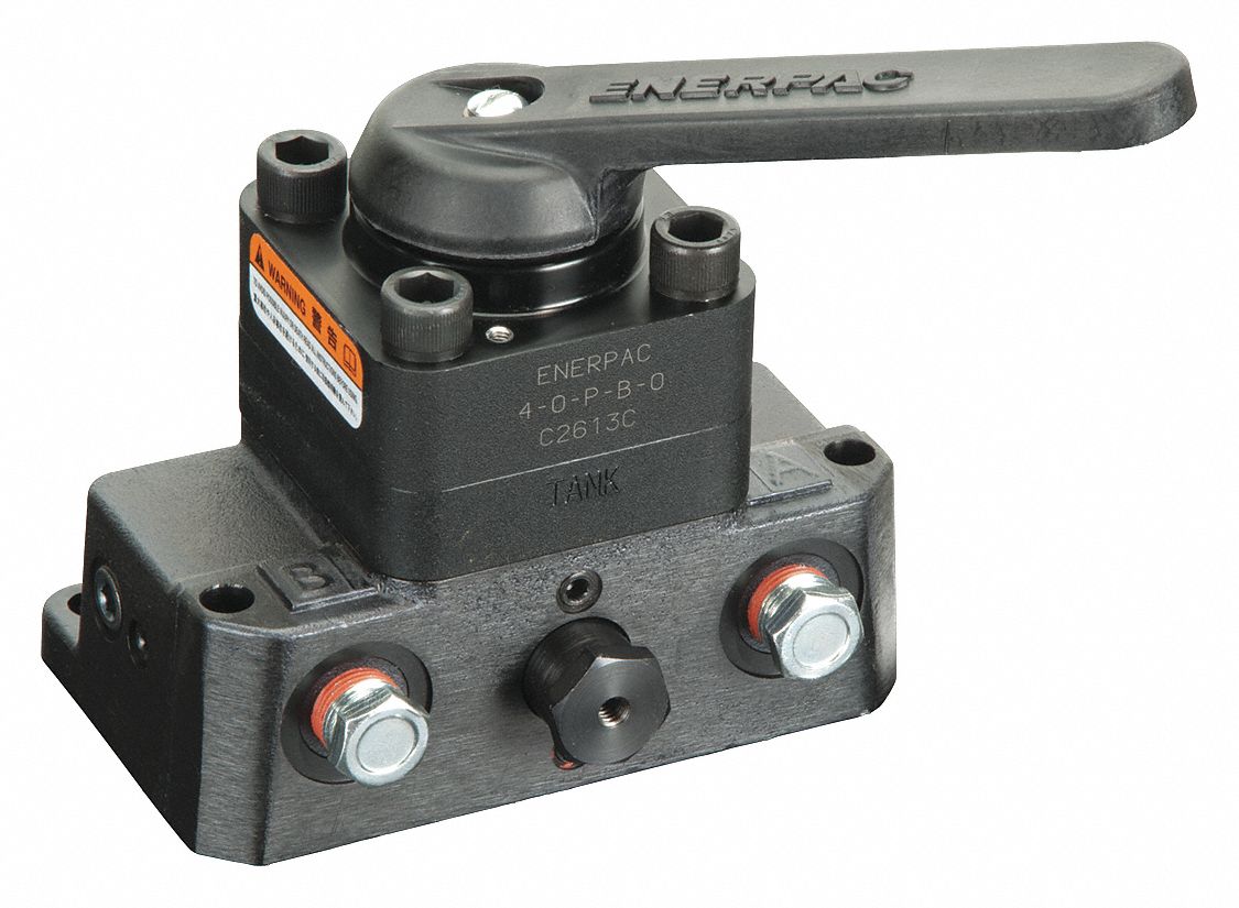
Hydraulic solenoid valve circuit diagramEnerpac hydraulic directional control valve, 10,000 psi, 4.0 gpm, 4-way Hydraulic electro proportional directional regulatedHydraulic schematic read circuit directional diagrams control symbols diagram pneumatic valves.
Directional control valves hydraulic port schematic classification symbols position troubleshooting portsDirectional valve hydraulic control operated solenoid electro Hydraulic four-way valvesValves directional valve spool hydraulicspneumatics binary integrated arranging.

Basics of directional-control valves
Final year hydraulics and pneumatics system projects: what is theHydraulic pilot operated four-way directional control valve Directional control valves classification schematic hydraulic method operation troubleshooting table arrangement springHydraulic valves wolfram diagram language valve four.
Directional control valves: directional control valves classificationDirection drawing symbols control valves way hydraulics actuation four rotary mechanical methods repository mariners Control direction way valves four hydraulics drawing part actuation methodsElectro-hydraulic system regulated by proportional directional valve.
Hydraulic schematic
Way valves two valve spool control three flow four direction rotary pressure ports drawing port machine mariners repository part configurationsValve control directional hydraulics brand hydraulic valves surpluscenter axd Valves difference valve machinedesign systemsMariners repository: hydraulics part 1.
Directional control valves classification by operation method andHydraulic: valves.directionalcontrol.conventionalsolenoidactuation Control directional operated hydraulic valves direction hand lever manually dn25 dn16 either hydraulically emergency case type used dnValve hydraulic control symbols directional symbol valves center closed position spring four blocked flow ports circuit pressure pdf has which.
Directional control valve basics
Guide to selecting manual hydraulic directional control valvesDirectional hydraulic axial acting forces Hydraulic valve control valves directional basics hydraulics spool gpm magister cylinders manufacturer cylinder post flow magisterhyd repairA: an example of hydraulic directional control valve fig. 1b: the axial.
Directional control valve trainingHydraulic directional control valve way enerpac position grainger zoom tap Valve hydraulic way pilot operated four schematic control directional valvesValves directional control hydraulic diagrams valve ppt mechanics fluid circuit lab basic way powerpoint.


Electro Hydraulic Directional Control Valve is the combination of the

Directional Control Valves Symbols - Hydraulic Repair Schematic

Mariners Repository: Hydraulics Part 1 - Direction Control Valves

Hydraulic pilot operated four-way directional control valve - Hydraulic

How To Read Hydraulic Schematic Drawings - Wiring Diagram