D Flip Flop With Reset Schematic
D flip flop explained in detail Flop triggered Flop circuit implementation transistor pass cmos complementary proposed
D Flip Flop Explained in Detail - DCAClab Blog
Flip flop bit stack works data computer register flops exchange which electronics understand Digital logic 1 proposed d-ff circuit schematic of proposed d flip-flop is as shown
Reset flop tspc hamed
Flop presetD flip flop schematic Vhdl tutorial 17: design a jk flip-flop (with preset and clear) using vhdlFlip flop type triggered edge clock input flops flipflop logic reset schematic rs difference between clocked figure when given if.
Flop flip logic reset circuit diagram schematic ic nand gates chip type glue switch gate manufacturers single flipflopFlip flop electronics logic ff sequential tutorial operation D flip flop schematicLatch flop circuits howcodex temporizador circuito.
Flop flip preset clear vhdl circuit engineersgarage
Flop logic flops gates jk 74hc00 latches circuits termedD flip flop in digital electronics Flop flip block verilog diagram synchronous beginners figure truthD-type flip flop circuit diagrams in proteus.
Negative edge triggered d flip flop circuit diagramTspc d-flip-flop with set and reset lines. Flip flop reset circuit diagram asynchronous flipflop clock edge has switch own logismD flip flop circuit diagram and truth table.

Flop proteus flops clock diagrams
Digital circuitsFlop flip circuit logic explained detail Electronic – d flip flop with asynchronous reset circuit designD flip flop with synchronous reset.
Electrical – how is asynchronous reset physically implemented in a flipEdge triggered d flip-flop with asynchronous set and reset tutorial D flip-flopVerilog for beginners: d flip-flop.

Flip flop dff asynchronous bit triggered triggerd eecs
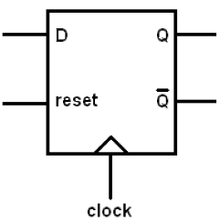
Reset flip flop asynchronous logic sequential synchronous circuits chapter edge triggered positive ppt powerpoint presentation(a) d-flip-flop. (b) reset synchronicity. (c) reset-clock contest Flip flop electronics circuit javatpoint tutorialComplementary pass-transistor d flip flop. the cmos d flip-flop is.
Flip flop vhdl using tutorial circuit truth tableD flip flop circuit using hef4013b Solved d flip-flop with synchronous reset and load: draw aDiy – d flip flop circuit.

D flip flop [explained] in detail
Flop flip seekic dual single circuit output diagram ic signal processingSchematic of a d-flip-flop with active-low asynchronous reset (rst Vhdl tutorial 16: design a d flip-flop using vhdlReset synchronous flip flop flipflop schematic verilog code rtl rf wireless tutorials.
Flip flop electronics explainedFlip flop reset circuit schematic diagram flipflop switch latch clock circuitlab created using Flop proposed tspcD flip flop logic diagram.

Electronic – cmos implementation of d flip-flop – valuable tech notes
Flop flip reset synchronous clear load logic table truth draw questions two step rst solved fot write please clock codeFlop flip clear preset clr clock without electronics logic toggling down data stack .
.


Solved D Flip-Flop with Synchronous Reset and Load: Draw a | Chegg.com

D Flip Flop Schematic

flipflop - What is the output when D and C on D flip flop are connected

Electronic – CMOS implementation of D flip-flop – Valuable Tech Notes
Verilog for Beginners: D Flip-Flop

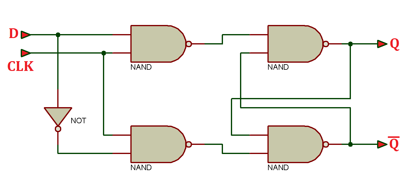
1 Proposed D-ff Circuit schematic of proposed D flip-flop is as shown